RF
Links, matching, connectors, and bench measurement, so the RF section can be checked on its own.
About
This page describes technical roles and the way work is organized. It is not a staff directory. Names and portraits will be added only after the company provides material that can be published.
Roles
Links, matching, connectors, and bench measurement, so the RF section can be checked on its own.
Firmware, drivers, and the data path on the device, connected to an SDR or host software.
Programmable logic, clocks, and custom I/O, so different interfaces share one timing plan.
Requirements, verification items, and the introduction sequence, so the sections still fit when they are brought together.
Method
A discussion starts by writing down the direction of the data, the equipment already in place, and the constraints. The work is then split into RF, logic, and software. The prototype checks those agreements. It does not stand in for specifications that are still open. Introduction and later changes come after that check.
To match this to a real requirement, use the inquiry form on the home page.
Tools
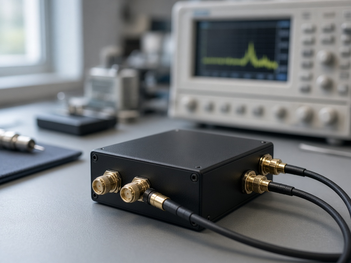
Boards and layout use Altium and KiCad. The RF section is checked with instruments for the link and matching.
Embedded work centers on C/C++, ARM, and FreeRTOS. FPGA work uses VHDL and Verilog with tools such as Vivado and Quartus, including on-chip buses such as AXI.
Device connectivity may involve BLE, Wi-Fi, MQTT, REST, and TLS. Timing discussions can include PTP, 1PPS, and GNSS time references. Use depends on the project.
Software and logic start with unit tests and hardware-in-the-loop checks. Hardware is reviewed for manufacturability and testability. Certification names are omitted where no evidence is published here.
© XingYi Precision Technology Co., LTD. All Rights Reserved.