Technology

SDR and FPGA

Both items present communications and interface integration. There is no fixed model number, and no unpublished power, band, or protocol figure.

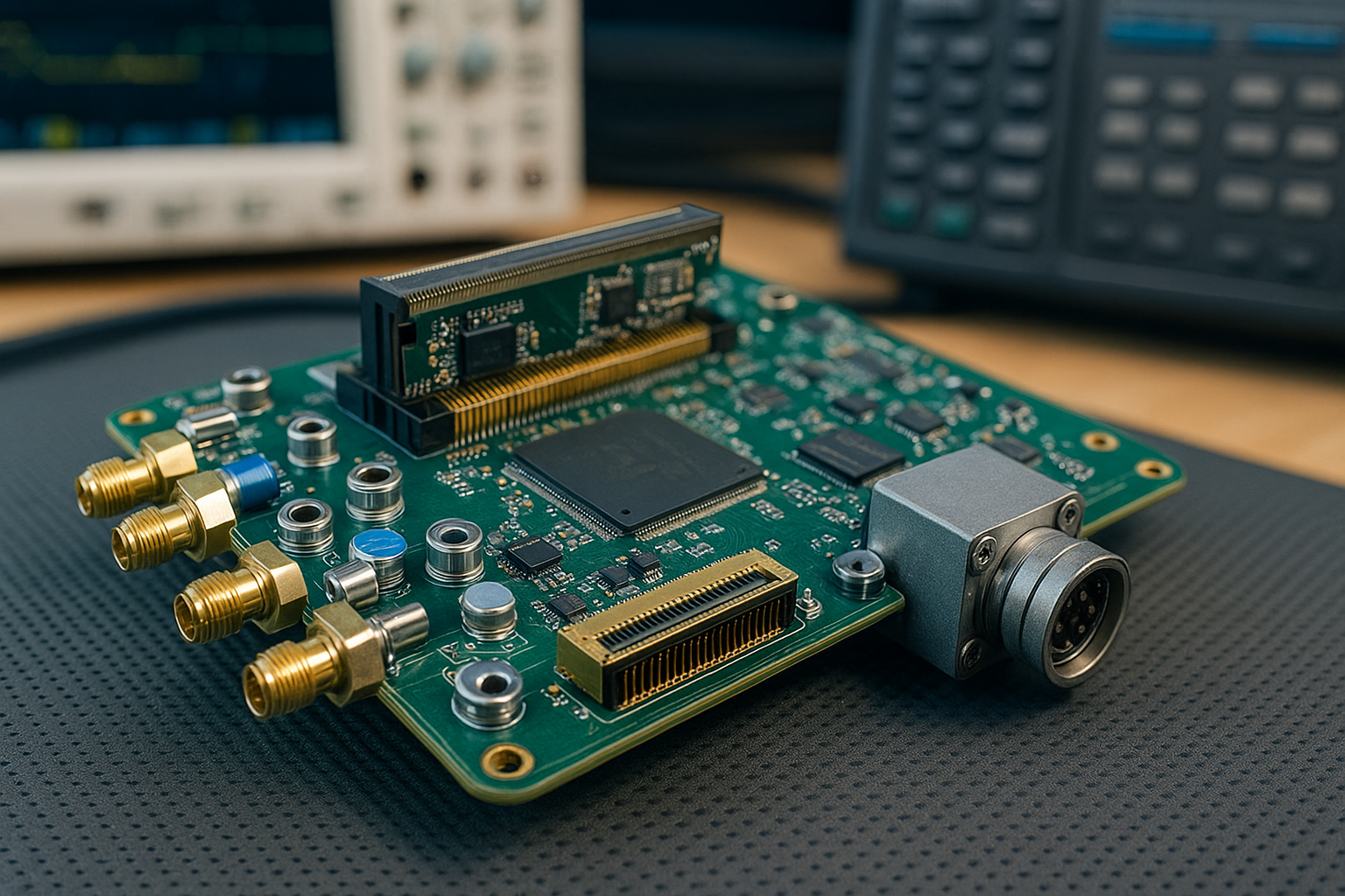
Page header uses a circuit-board stock image, not a product photo.

Overview

Software-defined radio

A programmable radio for the RF front end, baseband, and the external data or control interface. It fits work where the link is still being defined and a measurable prototype comes before a production specification.
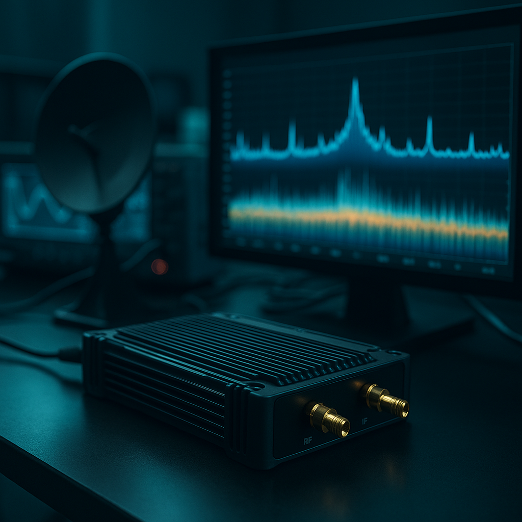
Illustration, not company hardware or a measured result.

Technical points

  • RF, baseband, and the external interface can be discussed separately, then placed on one platform where that helps.
  • A prototype phase can include instrument measurements and a check of the data path.
  • If timing affects the link, it is written into the approach rather than added later.

When it fits

Existing equipment needs an adjustable RF or data link, and the first deliverable should be a prototype that can be verified rather than a locked production specification.

How the pieces connect

  1. Host or controller
  2. SDR
  3. RF front end
  4. Far-end equipment

Specifications

No fixed public specification is available. The rows below are items confirmed during an inquiry, not measured values.

Band and power
Confirmed per inquiry
RF or data connector
Confirmed per inquiry
Clock and synchronization
Confirmed per inquiry
Host interface
Confirmed per inquiry

Back to the inquiry form

Overview

FPGA interfaces

Programmable logic for bridging interfaces, setting clocks, and holding custom I/O once the project needs it. It fits cases where the data path between existing equipment and a new system is not settled.

Technical points

  • Interfaces and clocks can follow the equipment being connected.
  • Custom I/O is added only after the requirement is clear. No specific bus is assumed.
  • Logic and embedded software can be given separate responsibilities during integration.

When it fits

The electrical or data interfaces on the two ends do not match, so programmable logic has to bridge them and the timing requirements have to become verification items.

Illustrative board, not company hardware.

How the pieces connect

  1. Host or controller
  2. FPGA
  3. Custom I/O
  4. Far-end equipment

Specifications

No fixed public specification is available. The rows below are items confirmed during an inquiry, not measured values.

Host interface
Confirmed per inquiry
Clock and synchronization
Confirmed per inquiry
Custom I/O
Confirmed per inquiry
RF or data connector
Confirmed per inquiry

Back to the inquiry form

© XingYi Precision Technology Co., LTD. All Rights Reserved.